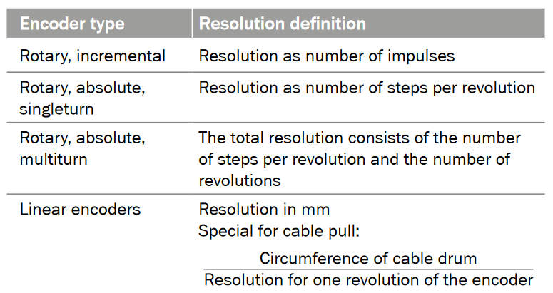
Absolute encoders
Absolute encoders generate information about position, angle and rotation counts in type-specific angle steps. For this, a unique code pattern is assigned to each angle increment. The number of code patterns available per revolution determines the resolution. Each code pattern forms a unique reference, and is therefore absolute position information. There is therefore no need for a reference run after switching on. A single-turn encoder measures the absolute position within a revolution. A multi-turn encoder not only provides the position within a revolution but also the number of revolutions.
Analog signal – Sin/Cos connection
In signaling theory, an analog signal is an infinite, continuous signal. An analog signal is described as smooth. Outputs depend on the type of device.
• Absolute encoders: a current signal of 4mA to 20mA or a voltage
signal of 0 to10 Volt.
• Incremental encoders: sine-cosine signal
Baud rate
Gives the signal rate and hence the speed of serial data transfer in bits per second.
Bend radius
In cabling terms, the bend radius relates to the smallest curve radius a cable may have when installed, without the cable properties being altered. The bend radius is given in relation to the cable diameter.

Binary code
Type of code used to output information on the absolute position.
Bus system
A system for transferring data between multiple devices over a common cable. A bus system makes it possible to control all sensors and actuators centrally. Additional information such as process data, service data and diagnostics data can also be
exchanged.
Well known examples are:
DeviceNet, PROFIBUS, CANopen, PROFINET, EtherNet/IP, EtherCAT®. Additional information on bus systems can be found in this glossary under the CANopen, DeviceNet, EtherCAT®, EtherNet/ IP, PROFIBUS and PROFINET entries.
CANopen
CANopen: is a communication protocol based on CAN.
User organization: CiA (CAN in Automation)
More detailed information about this technology is available at: can-cia website.
Channel
Signal path upon which a signal is output.
Code type
Unique encoding of the measured values according to a defined scheme at the encoder output. In practice, different codes are used for different electrical interfaces, e.g., SSI interface with Gray code.
Coefficient of thermal expansion
This describes the behavior of a material in relation to changes of its dimensions as influenced by changes in temperature.
DC (diagnostic coverage)
Safety characteristic
Measure of the effectiveness of the diagnostics that can be determined as the ratio of the failure rate of detected dangerous failures to the failure rate of all dangerous failures.
DeviceNet
DeviceNet is a CAN based communication protocol. User organization: ODVA More detailed information about this technology is available at: odva website.
Diagnostic functions
Absolute encoders with diagnostic functions provide diagnostic data in addition to standard encoder data (e.g., position). This includes information like the minimum and maximum temperature, an operating hour counter, a counter for changes in direction, and lots more. The diagnostic functions are available in most absolute and wire draw encoders with fieldbus or Ethernet- base fieldbus interfaces.
Differential evaluation
Evaluation of signals of an output stage for which the inverted signals are also output. The 1/0 level, or sine/cosine signals are transferred in the form of voltage differences between two cables. In this way, the signal used (the difference) remains uncorrupted as interference normally affects both cables equally.
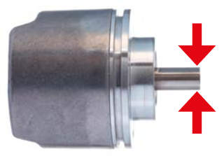
Drum circumference
The resolution in mm of a wire draw encoder can be determined using the circumference of the bobbin and the resolution of the rotary encoder (e.g. 12 bits per revolution).
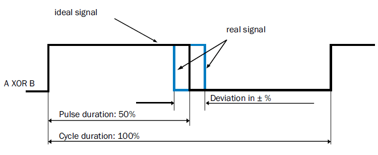
Duty cycle/pulse-pause ration
Errors related to rising to falling signal edges from a square wave signal will affect the encoder’s jitter.
EMC
Electromagnetic compatibility (EMC) means that technical equipment should not be affected by electromagnetic interference. This is achieved both by limiting sources of interference in devices and by devices being designed to be sufficiently resistant to interference. EMC is regulated by EU Directives and Standards.
Enclosure rating
The enclosure rating indicates the degree of protection of a machine or sensor against contact and penetration by impurities and water. The enclosure ratings begin with the letters IP, followed by the first digit, which indicates the degree of protection provided against touch and impurities. The second digit describes the protection against penetration by water.
Encoders
Encoders are sensors for monitoring position, angle and speed. Essentially, encoders can be categorized as rotary or linear. Rotary encoders are sub-divided into incremental and absolute encoders. Linear encoders are further sub-divided into wire draw encoders and non-contact linear encoders.
Error limits
The error limit is the largest positive or negative deviation of any angle position (absolute) or of a measured angle (incremental) from the true value.
EtherCAT®
EtherCAT® is an Ethernet based fieldbus.
User organization: EtherCAT® Technology Group
More detailed information about this technology is available at: ethercat website.
EtherNet/IP
EtherNet / IP is an Ethernet based fieldbus.
User organization: ODVA
More detailed information about this technology is available at: odva website.
Fieldbus
Bus system in the process area for direct connection of sensors and actuators that have their own intelligence. Data in digital form is transferred between sensors, actuators and control devices via a fieldbus. This transfer must be as rapid as possible, i.e., in real time. For this, a fixed minimum and maximum response time must be guaranteed.
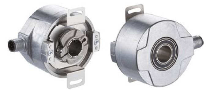
Flange
Part of the encoder for fixing to the customer installation interface. There are various mechanical designs available, for example:

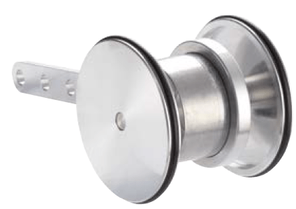
Flange adapter
Mechanical adapter for ensuring that an encoder flange is mechanically compatible with the customer’s mechanical interface.
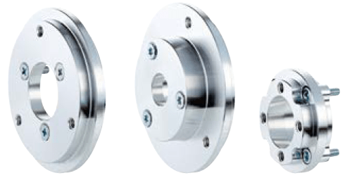
Center = Flange adapter for a 20 series face mount flange to a 36 series face mount flange; Right = Special flange adapter.
Gray code
Constant code that is also used with the SSI interface. When one value is changed for the next one, the data bit changed is the specific one that will allow data transfer to take place reliably.
Gray excess code
If a suitable section is extracted for encoder resolution from the middle of the complete Gray code, this results in the “Gray Excess Code” (capped Gray code). The use of this Gray excess code allows only a single data bit to be altered even when the encoder crosses zero, although the number of steps is not 2 n where n is a whole number.
Halogen-free (connectivity)
Cables and wiring are said to be halogen-free if the materials used do not contain salt forming chlorine, fluorine, bromine or iodine. The insulation and sheath materials of these cables consist of polymers based on pure hydrocarbons. When such materials are burned, no corrosive or toxic gases are produced, but only water vapor and carbon dioxide.
HIPERFACE®
High Performance Interface (HIPERFACE®) is a hybrid interface developed by SICK that can transfer analog speed values and digital position values. Electrical compatibility is guaranteed by the use of HIPERFACE® as the obligatory interface for all physical parameters. The advantages of HIPERFACE® are that only one interface is required on the speed regulator for all applications, only one type of signal cabling is needed between the speed regulator and the signal encoder and manual configuration of the speed sensor is not necessary.
HIPERFACE DSL®
The High Performance Interface DSL is a pure Digital Servo Link interface developed by SICK that provides new servo drive system architecture for HIPERFACE® with a completely new range of options as it is not hybrid (analog/digital), but is completely digital.
Thanks to the innovative and interference-free HIPERFACE DSL® protocol, rugged and reliable communication can be achieved using just two wires that are integrated into the motor cable. In addition, the digital protocol requires a minimum of connection
cables between the frequency inverter and the motor feedback system.
The absence of motor feedback connections achieves significant cost savings and distinctly increased performance.
HTL Push Pull
High Voltage Transistor Logic functions with a voltage supply in the range 10 and 30 V DC, with 24 V DC being the most common. “Low” is defined as an output of between 0 VDC to 3 VDC and “high” as between (Us – 3.5 VDC) … Us.
Hysteresis
Hysteresis is defined as the maximum spread of several consecutive positioning processes taken for one point from several different directions under identical conditions.
Incremental encoders
Incremental encoders generate information about position, angle and rotation counts. The number of lines per revolution determines the number of impulses that the encoder transmits to the control unit for each revolution. The current position can be determined by the control unit by counting these impulses from a reference point. When the machine is switched on, a reference run to the reference point is required to determine the actual position of the encoder.
Initialization time
Amount of time following the supply voltage being connected and the encoder outputting a valid signal.
Interface, electrical
Connection point between two devices or systems. The devices or systems on either side of an interface are connected to each other by interface cabling over which data, addresses and control signals are exchanged. The term interface embraces the complete functional, electrical and constructive conditions that make up the point of contact between the devices or systems. Depending on the type of data transfer, a distinction must be made between parallel (e.g., Centronics, IEEE 488) and serial interfaces (e.g., RS-422, RS-423, RS-485) that are designed for differing transfer speeds and distances.
Inverted signal
Reciprocal signal for the suppression of interference impulses when using differential sampling.

Jitter
From the English verb “to jitter”: flicker, tremble; time variation of the output signal resulting from constantly present tolerances.
Linear encoders
A linear encoder is used for frictionless length measurement and determining positions. A read head samples a code pattern or the magnetic field of a magnetic scale and outputs the appropriate electric signal.
Linearity
The accuracy of wire draw encoders is described by the linearity. This indicates the maximum deviation for the measurement of a defined measurement distance. In contrast to repeatability, this relates to the measuring range covered and not to a
positioning point.
Load current
Maximum amount of current permitted to flow through each channel of an incremental encoder.
Material resistance, PUR
Flexible silicone and halogen-free cabling with PUR outer sheath: The oil and fire resistance requirements of VDE 0472 are fulfilled. Can be used in drag chain applications with a minimum bend radius. This cabling is most suitable for flexible use
in robot technology, for machine tools, as well as for machining production.
Material resistance, PVC
Pure PVC cables, suitable for medium mechanical strain in packaging machines as well as for assembly and production lines: good resistance to acids and alkalis and hence ideal for use in the food and beverage industries. Resistance to wear as well as oil and chemical resistance is limited.
Maximum output frequency
The maximum encoder output signal frequency, for which the correct sequence of the code values is assured is called the maximum output frequency. The formula used is as follows:

Measurement increment deviation
The measurement increment deviation indicates the maximum measurement deviation from measurement increment to measurement increment. For this, measured values are taken at one or more adjacent positions in the test range and their maximum deviation from the desired value determined.

Measurement step
There is a differentiation here between the measurement step for absolute and incremental measurement systems.
Incremental measurement systems:
In this case, the measurement step represents the period of the output signal. Here, the number of periods is the same as the number of graduations per revolution on the measurement scale, or a multiple thereof.
Absolute measurement systems:
In this case the measurement step is the smallest possible angular movement of the rotor that will produce a change in the output signal.
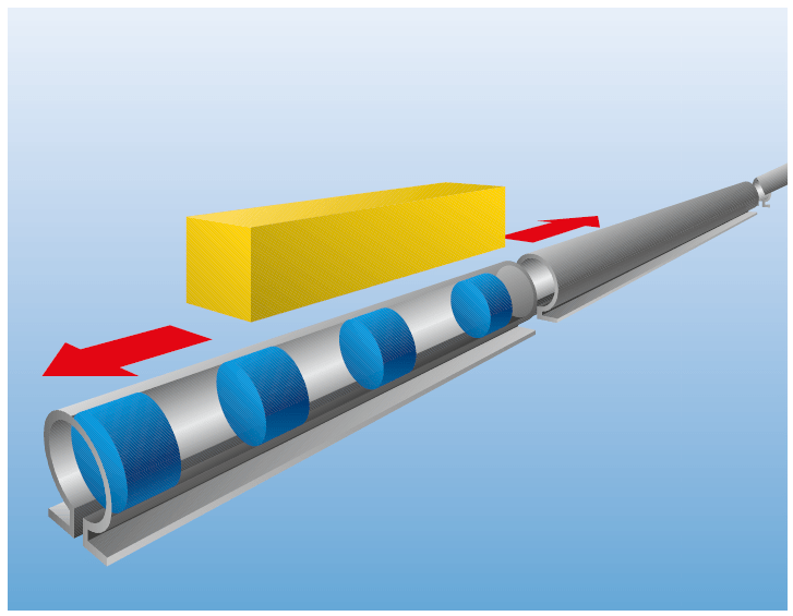
Measuring element
To determine a position, linear encoders require measuring elements that are installed along the entire length of the measurement path. The code pattern is formed by various magnet properties that are scanned by magnetic sensors in the read head.
Measuring range
The range within which a rotary or linear encoder can produce a valid measurement signal.
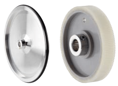
Measuring wheel
Mechanical assembly that enables rotary encoders to record linear movements. If you wish to use a measuring wheel, you can either use a full measuring wheel system, like the DFV60, or a rotary encoder with a separate measuring wheel accessory.
MTTFd value (mean time to failure)
Safety characteristic
Expected value for the mean time to dangerous failure
(ISO 13849-1/EN ISO 13849-1).
Multiple sampling
Increasing the number of impulses for an incremental encoder following evaluation by the customer.
Individual sampling
Evaluation of rising signal edges of an encoder channel (A or B).
Dual sampling
Evaluation of rising and falling signal edges of an encoder channel (A or B).
Quadruple sampling
Evaluation of rising and falling signal edges of both encoder channels (A and B).
Multiturn (MT)
A type of absolute encoder that in addition to the angular position of the shaft (singleturn) can also definitively determine and output the number of shaft rotations (multiturn).

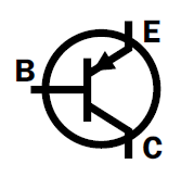
NPN output (Open Collector)
NPN output is an interface based on an output circuit with NPN
transistor.

Offset
The difference between the actual physical value and the preset value is described as the offset. This can be both a position offset for position measurement, as well as a voltage offset.

Open Collector
An open collector is the unconnected collector connection of a transistor, whose emitter is connected to earth and whose collector is connected to the output. Signals can be output using NPN or PNP transistors.
Operating torque
The torque required to move a shaft at a constant speed.
PFHd (probability of dangerous failure per hour)
Safety characteristic
Mean probability of a dangerous failure per hour (1/h).
PL (performance level)
Safety characteristic
Discrete level used to specify the ability of the safety-related parts of a control system to perform a safety function under foreseeable conditions (ISO 13849-1/EN ISO 13849-1).
PNP output (Open Collector)
The PNP output is an interface based on an output circuit with a PNP transistor.
Position forming time
The amount of time following detection of an absolute position until the next absolute position can be detected by the absolute encoder.
Preset
For absolute encoders, a preset value can be allocated to the actual physical position value. In the case of an allocation via the set cabling, this equates to the value 0. For programmable absolute encoders, the preset value can be any value within the measuring range.
PROFIBUS
PROFIBUS is a fieldbus for industrial communications.
User organization: PNO (PROFIBUS Nutzerorganisation e. V.) More detailed information about this technology is available at: profibus website.
PROFINET (Process Field Network)
PROFINET is an Ethernet based fieldbus.
User organization: PNO (PROFIBUS Nutzerorganisation e. V.) More detailed information about this technology is available at: profibus website.
Programming options for encoders
Many SICK encoders can be programmed by the customer. This means that customers can modify the encoder’s parameters to better suit the application in question. The following options are available for programming:
- Hand-held programming tool (for incremental and SSI absolute encoders)
- PC-based programming tool (for incremental and SSI absolute encoders)
- Web-server-based programming (absolute encoders with an EtherNet/IP interface)
- Programming options using the engineering software issued by the manufacturer of the control unit (fieldbus and Ethernet encoders)
- RS-485 programming option (for incremental and SSI absolute encoders)
Programming tool
Programming device for configuring encoders. Programming devices for encoders can be used for either incremental encoders or absolute SSI encoders. A variety of programming tools are available, for example the PGT-08-S PC-based programming tool or the PGT-10-P hand-held device.
Reproducibility
Reproducibility or repeatability is defined as the maximum spread of several consecutive positioning processes taken for one point from one direction under identical conditions.
Resolution
The resolution is expressed as the number of impulses/steps per revolution or path units.
If, for example a rotary incremental encoder has a resolution of 12 bits, this means the number of impulses is 4,096.The formula for calculation is: Number of impulses = 2X, where x is the resolution in bits.
Rotary encoders
A type of encoder that records rotational movements. Rotary encoders are available as incremental encoders and as absolute encoders.
Rotation direction, clockwise (cw)
Rotation to the right, when viewing the shaft.
Rotation direction, counterclockwise (ccw).
Rotation to the left, when viewing the shaft.
Rotor moment of inertia
The moment of inertia that is generated by the rotor mass (made up of the shaft and other parts) in a rotary encoder.
RS-485
RS-485 or EIA-485 is an interface standard used for transmit-ting data. Various electrical interfaces, such as PROFIBUS, are based on the RS-485 standard. Programmable incremental and absolute SSI encoders by SICK can be programmed using RS-485 commands.
Safety encoders
SICK safety encoders are encoders for use in functional safety technology. They generate information about position, angle, and revolution counts. Rotary safety encoders are sub-divided into incremental and absolute encoders. When combined with safety controllers, safety encoders support the realization of safety functions. The encoders are certified safety products and are characterized by safety technology parameters such as safety integrity level (SIL) or performance level (PL).
Scaling
For programmable encoders, the encoder’s actual value is multiplied by a scaling factor. This means that the resolution can be adapted to the application in question.
Scanning, magnetic
Position, angle and speed determination for rotary or linear en-coders using permanent magnets and appropriate evaluation units to determine the magnetic field. Encoders with magnetic scanning are usually of lower resolution than optical ones.

Scanning, optical
Position, angle and speed determination for rotary or linear encoders using LEDs, code patterns and photo-diodes. The graduation marks (for incremental encoders) or codes (for absolute encoders) are inscribed as digital patterns on a glass, metal or plastic disc and are sampled by a light source (light emitting diode) and photo-diodes.Encoders with optical scanning are usually of higher resolution than magnetic ones.

Service life
For rotary encoders, the service life of the bearings represents the overall service life of the encoder expressed in revolutions.For wire draw encoders, the service life is expressed as the total number of cycles. A cycle is defined as one withdrawal and rewind movement (load cycle).
The service life depends on the type of load. This is influenced by factors such as the environment, the installation location, the measuring range in use, the travel speed and acceleration. If the value of one or more of these influencing factors is in the high range, the service life may be reduced proportionally.
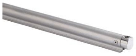
Shaft
The component of a rotary encoder that transfers the rotation movement and torque from the application to the sensor unit of the encoder.
Shaft coupling
A shaft coupling is for the indirect connection of two shafts to balance radial, axial or angular offset.

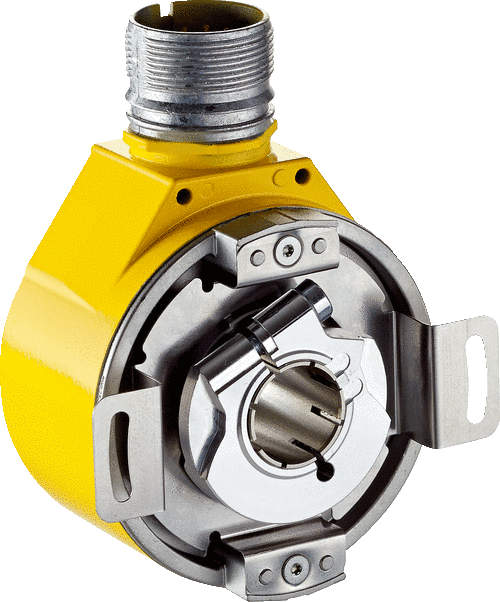
Shaft load capacity, axial
The axial shaft load capability describes the load capacity along the axis of the encoder shaft.
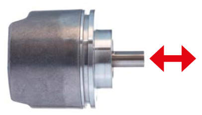
Shaft load capacity, radial
The radial shaft load capability describes the load capacity about the radius along the encoder shaft. For this, the point of action must be applied to the end of the shaft.
Shaft offset, static / shaft movement, dynamic, for hollow shafts
Static
Radial and/or axial shaft offset resulting from the tolerance of the customer’s flange.
Dynamic
Radial and/or axial shaft offset resulting from concentricity errors and measurement changes caused by the temperature and/or clearance of the customer’s shaft during operation.
Shield
The shielding of equipment or connecting cables is the design-dependent protection of equipment against radiated electromagnetic interference. Sensitivity to radiated electromagnetic interference, as well as the intensity of radiated electromagnetic interference, must be reduced by full shielding so that the encoder can by used properly. This should be extensive and all around.
SIL (Safety Integrity Level)
Safety characteristic
Discrete level (one out of a possible three) for specifying the safety integrity of the safety functions assigned to the safety-related system, where safety integrity level 3 has the highest level of safety integrity and safety integrity level 1 has the lowest (IEC 62061/EN 62061).
SILCL (SIL claim limit)
Safety characteristic
Safety integrity level claim limit (for a subsystem): Maximum SIL that can be claimed for an SRECS subsystem in relation to architectural constraints and systematic safety integrity (IEC 62061/EN 62061).
Silicone-free (connectivity)
Silicone-free connections must be used in certain industrial fields, such as paint shops. The reason for this is that silicones can reduce the effectiveness of or disrupt adhesive or other joints.
Sine-cosine interface
Unlike conventional pulse signals, sine-cosine signals are emit-ted in sine-wave form. These signals can be emitted in a higher resolution, as there is also an option to sample the signals using an analog-digital converter. For this reason also, encoders with sine-cosine interfaces are preferred for demanding servo applications for which a high level of accuracy is required. In addition to the signals, a zero set can also be emitted, from which the absolute position can be calculated.
Singleturn (ST)
A type of absolute encoder that can definitively determine and output the angle position within a single revolution.
Square-wave signal – HTL/TTL
A square-wave signal refers to a periodic signal that alternates between two values and appears as a square-shaped waveform over time. This signal is used in encoders with incremental interfaces in the form of HTL and TTL signals.
SSI
A synchronous serial interface is an interface originally developed by Max Stegman GmbH (now SICK) for serial data transfer that makes it possible to transmit absolute positions. The advantage of this type of transfer is that, as well as the time of the recording of the position, the speed of the data transfer can be controlled by this SPS. This guarantees safe transfer.

