By OMRON.
What is a proximity sensor?
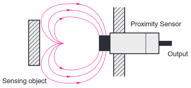
“Proximity Sensor” includes all sensors that perform non-contact detection in comparison to sensors, such as limit switches, that detect objects by physically contacting them. Proximity sensors convert information on the movement or presence of an object into an electrical signal. There are 3 types of detection systems that do this conversion: systems that use the eddy currents that are generated in metallic sensing objects by electromagnetic induction, systems that detect changes in electrical capacity when approaching the sensing object, and systems that use magnets and reed switches.
A proximity switch is a sensor able to detect the presence of nearby objects without any physical contact. A proximity sensor often emits an electromagnetic field or a beam of electromagnetic radiation (infrared, for instance), and looks for changes in the field or return signal. The object being sensed is often referred to as the proximity sensor’s target.
The Japanese Industrial Standards (JIS) define proximity sensors in JIS C 8201-5-2 (Low-voltage switchgear and controlgear, Part 5: Control circuit devices and switching elements, Section 2: Proximity switches), which conforms to the IEC 60947-5-2 definition of non-contact position detection switches.

JIS gives the generic name “proximity switch” to all sensors that provide non-contact detection of target objects that are close by or within the general vicinity of the sensor, and classifies them as inductive, capacitive, ultrasonic, photoelectric, magnetic, etc.
An inductive proximity sensor is a type of non-contact electronic proximity sensor that is used to detect the position of metal objects. The sensing range of an inductive switch is dependent on the type of metal being detected.
In electrical engineering, capacitive sensing is a technology, based on capacitive coupling, that can detect and measure anything that is conductive or has a dielectric different from air. Many types of sensors use capacitive sensing, including sensors to detect and measure proximity, position or displacement, humidity, fluid level, and acceleration.
Ultrasonic sensors use sound waves rather than light, making them ideal for stable detection of uneven surfaces, liquids, clear objects, and objects in dirty environments. These sensors work well for applications that require precise measurements between stationary and moving objects.
A photoelectric sensor, or photo eye, is an equipment used to discover the distance, absence, or presence of an object by using a light transmitter, often infrared, and a photoelectric receiver. They are largely used in industrial manufacturing. There are three different useful types: opposed (through beam), retro-reflective, and proximity-sensing (diffused).
Magnetic sensors detect changes and disturbances in a magnetic field like flux, strength and direction. From established knowledge about the existing magnetic field and the data collected from sensors regarding changes and alterations, many things can be known. Rotation, angles, direction, presence and electrical current can all be monitored.
This technical explanation defines all inductive sensors that are used for detecting metallic objects, capacitive sensors that are used for detecting metallic or non-metallic objects, and sensors that utilize magnetic DC fields as proximity sensors.
Features
1. Proximity sensors detect an object without touching it, and they therefore do not cause abrasion or damage to the object.
Devices such as limit switches detect an object by contacting it, but proximity sensors are able to detect the presence of the object electrically, without having to touch it.
2. No contacts are used for output, so the sensor has a longer service life (excluding sensors that use magnets).
Proximity sensors use semiconductor outputs, so there are no contacts to affect the service life.
3. Unlike optical detection methods, proximity sensors are suitable for use in locations where water or oil is used.
Detection takes place with almost no effect from dirt, oil, or water on the object being detected. Models with fluororesin cases are also available for excellent chemical resistance.
4. Proximity sensors provide high-speed response, compared with switches that require physical contact.
5. Proximity sensors can be used in a wide temperature range.
Proximity sensors can be used in temperatures ranging from −40 °C to 200°C.
6. Proximity sensors are not affected by colors.
Proximity sensors detect the physical changes of an object, so they are almost completely unaffected by the object’s surface color .
7. Unlike limit switches, which rely on physical contact, proximity sensors are affected by ambient temperatures, surrounding objects, and other sensors.
Both inductive and capacitive proximity sensors are affected by interaction with other sensors. Because of this, care must be taken when installing them to prevent mutual interference. Care must also be taken to prevent the effects of surrounding metallic objects on inductive proximity sensors, and to prevent the effects of all surrounding objects on capacitive proximity sensors.
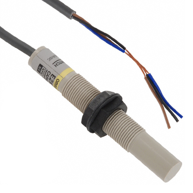
8. There are two-wire sensors.
The power line and signal line are combined. If only the power line is wired, internal elements may be damaged. Always insert a load.
Operating principles
Detection principle of inductive proximity sensors
Inductive proximity sensors detect magnetic loss due to eddy currents that are generated on a conductive surface by an external magnetic field. An AC magnetic field is generated on the detection coil, and changes in the impedance due to eddy currents generated on a metallic object are detected.
Other methods include aluminum-detecting sensors, which detect the phase component of the frequency, and all-metal sensors, which use a working coil to detect only the changed component of the impedance. There are also pulse-response sensors, which generate an eddy current in pulses and detect the time change in the eddy current with the voltage induced in the coil.
(Qualitative explanation)
The sensing object and sensor form what appears to be a transformer-like relationship.
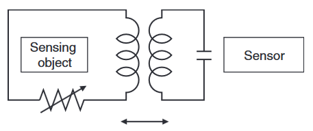
The impedance changes can be viewed as changes in the resistance that is inserted in series with the sensing object. (This does not actually occur, but thinking of it this way makes it easier to understand qualitatively.)
Detection principle of capacitive proximity sensors
Capacitive proximity sensors detect changes in the capacitance between the sensing object and the sensor. The amount of capacitance varies depending on the size and distance of the sensing object. An ordinary capacitive proximity sensor is similar to a capacitor with two parallel plates, where the capacity of the two plates is detected. One of the plates is the object being measured (with an imaginary ground), and the other is the sensor’s sensing surface. The changes in the capacity generated between these two poles are detected.

The objects that can be detected depend on their dielectric constant, but they include resin and water in addition to metals.
Detection principle of magnetic proximity sensors
The reed end of the switch is operated by a magnet. When the reed switch is turned ON, the sensor is turned ON.

Classification

Explanation of terms
Standard sensing object
A sensing object that serves as a reference for measuring basic performance, and that is made of specified materials and has a specified shape and dimensions.

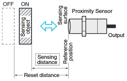
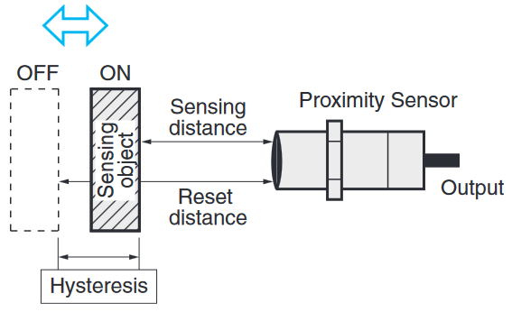
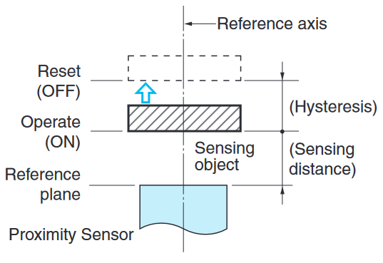
Sensing distance
The distance from the reference position (reference surface) to the measured operation (reset) when the standard sensing object is moved by the specified method.
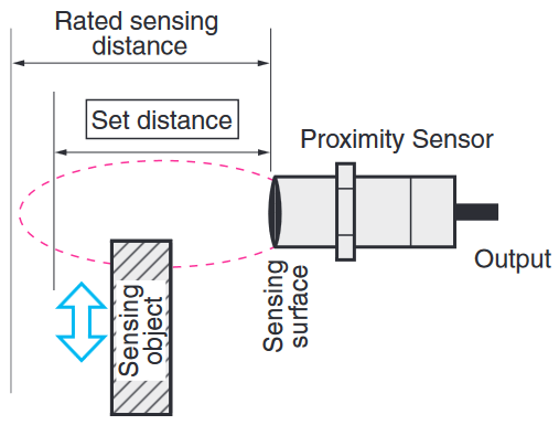
Set Distance
The distance from the reference surface that allows stable use, including the effects of temperature and voltage, to the (standard) sensing object transit position. This is approximately 70% to 80% of the normal (rated) sensing distance.
Hysteresis (Differential travel)
With respect to the distance between the standard sensing object and the sensor, the difference between the distance at which the sensor operates and the distance at which the sensor resets.
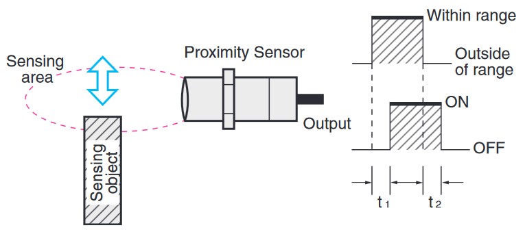
Response time
- t1: The interval from the point when the standard sensing object moves into the sensing area and the sensor activates, to the point when the output turns ON.
- t2: The interval from the point when the standard sensing object moves out of the sensor sensing area to the point when the sensor output turns OFF.
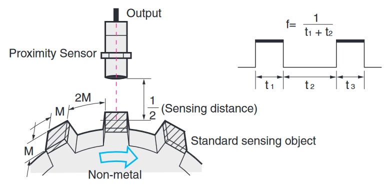
Response frequency
- The number of detection repetitions that can be output per second when the standard sensing object is repeatedly brought into proximity.
- See the accompanying diagram for the measuring method.
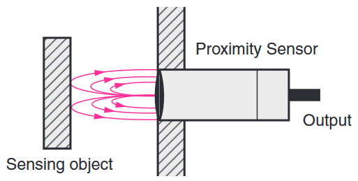
Shielded
- With a shielded sensor, magnetic flux is concentrated in front of the sensor and the sides of the sensor coil are covered with metal.
- The sensor can be mounted by embedding it into metal.
Unshielded
With an unshielded sensor, magnetic flux is spread widely in front of the sensor and the sides of the sensor coil are not covered with metal.
This model is easily affected by surrounding metal objects (magnetic objects), so care must be taken in selecting the mounting location.
Expressing the sensing distance
When measuring the sensing distance of a proximity sensor, the reference position and the direction of approach of the sensing object are determined as follows:
Cylindrical/rectangular sensors
Perpendicular sensing distance
Expressed as the measured distance from the reference surface when the standard sensing object approaches from the radial direction (perpendicular to the sensing surface).
Horizontal sensing distance and sensing area diagram
Expressed as the measured distance from the reference axis when the standard sensing object is moved parallel to the reference surface (sensing surface).
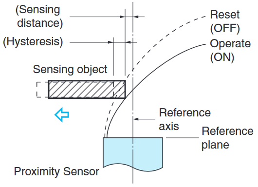
This distance depends on the transit position (distance from the reference surface), so it can be expressed as an operating point track. (Sensing area diagram)
Output configuration
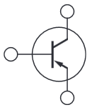
NPN transistor output
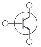
A general-use transistor can be directly connected to a programmable controller or counter.
PNP transistor output
Primarily built into machines exported to Europe and other overseas destinations.
Non-polarity/non-contact output
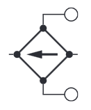
A 2-wire AC output that can be used for both AC and DC sensors. Eliminates the need to be concerned about reversing the polarity.
Take the following points into account when selecting a DC 2-wire model (polarity/no-polarity).
- Leakage current: A maximum current of 0.8 mA flows to the load current even when the output is OFF. Check that the load will not operate with this current.
- Output residual voltage: When the output is ON, voltage remains in the sensor, and the voltage applied to the load decreases. Check that the load will operate with this load voltage.
NO (normally open)
When there is an object in the sensing area, the output switching element is turned ON.
NC (normally closed)
When there is no object in the sensing area, the output switching element is turned ON.
NO/NC switchable
NO or NC operation can be selected for the output switching element by a switch or other means.
Interpreting engineering data
Sensing area

- This graph shows engineering data from moving the sensing object parallel to the sensing surface of the proximity sensor.
- Refer to this graph for proximity sensor applications, such as positioning. When a high degree of precision is required, use a separate amplifier proximity sensor.
Sensing distance vs. display values
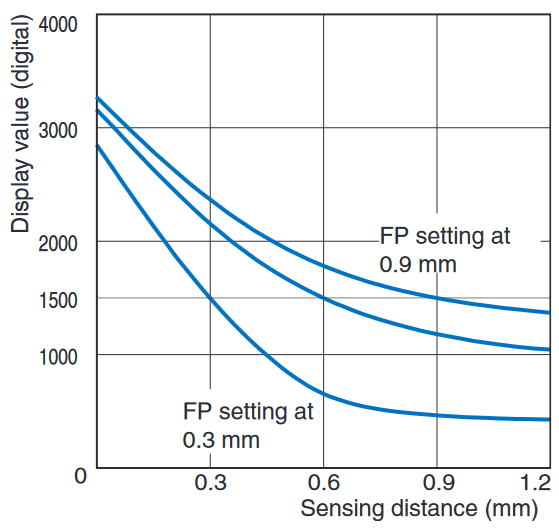
- This type of graph is used with separate amplifier proximity sensors. It shows the values when executing FP (Fine Positioning) at specified distances. FP settings are possible at any desired distance, with a digital value of 1,500 as a reference for OMRON E2C-EDA.
- The above graph shows numerical examples when FP (Fine Positioning) is executed at the three points of 0.3, 0.6, and 0.9 mm.
Influence of sensing object size and material
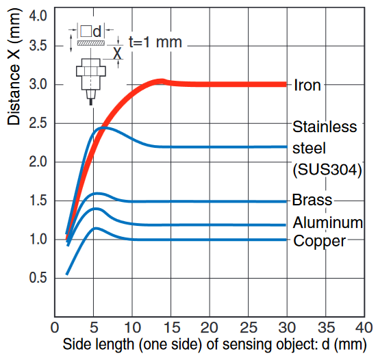
Here, the horizontal axis indicates the size of the sensing object, and the vertical axis indicates the sensing distance. It shows changes in the sensing distance due to the size and material of the sensing object. Refer to this data when using the same sensor to detect various different sensing objects, or when confirming the allowable leeway for detection.
Leakage current characteristics
- In contrast with contact-type limit switches, which have physical contacts, leakage current in a 2-wire proximity sensor is related to an electrical switch that consists of transistors and other components. This graph indicates the leakage current characteristics caused by transistors in the output section of the sensor.
- Generally speaking, the higher the voltage, the larger the leakage current. Because leakage current flows to the load connected to the proximity sensor, care must be taken to select a load that will not cause the sensor to operate from the leakage current.
- Be careful of this factor when replacing a limit switch, micro-switch, or other switch with a proximity sensor.
Residual voltage characteristics
Similar to leakage current characteristics, residual voltage is something that occurs due to electrical switches that are comprised of transistors and other components. For example, whereas the voltage in a normally open switch should be 0 V in the ON state, and the same as the power supply voltage in the OFF state, residual voltage refers to a certain level of voltage remaining in the switch. Be careful of this factor when replacing a limit switch, micro-switch, or other switch with a proximity sensor.
