Reactors can protect both motors and variable frequency drives (VFDs) from harmful current and voltage spikes. Reactors also help reduce power line distortion, known as harmonics, by adding impedance to the power system. A line reactor is placed in line at the point of use or just after a transformer to maintain a stable amperage to the user. When a line is disconnected from the system, the line reactor is also disconnected from the system. Quite often, line and load reactors are installed on AC drives without a solid understanding of why or what the positive and negative consequences are for adding this piece of hardware.
What are Line Reactors?
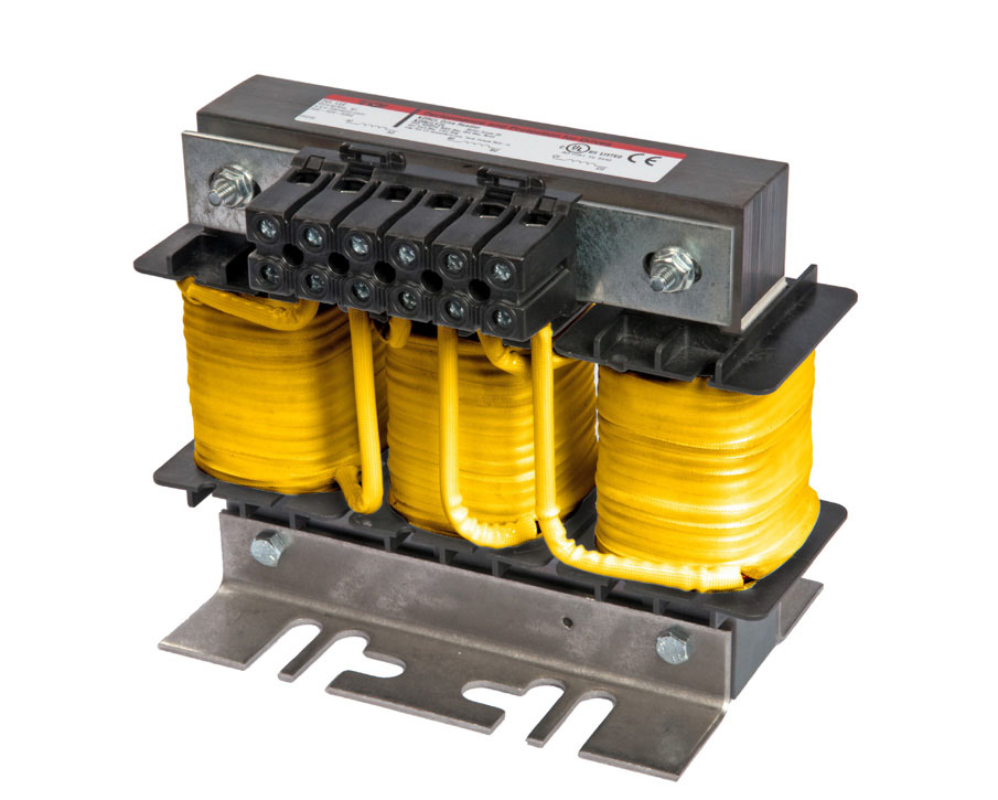
Quite simply, a 3-phase line reactor is an inductor wired in series between two points in a power system. A simple loop of wire is an air core inductor. More loops give a higher inductance rating. Reactors are simple electro-magnetic devices, some-times referred to as inductors. They consist of a steel core which is constructed of electrical grade steel laminations, and copper wound coils on each leg of a three-phase device. Each leg and coil represents a phase of a three-phase device and is simply wired in series with the variable frequency drive (VFD). Quite often some ferrous material such as iron is added as a core to the winding. This has the effect of concentrating the lines of magnetic flux there by making a more effective Inductor.
Line reactors are used to protect motors and reduce power line distortion (also referred to as dirty power) from variable frequency drives. Line reactors can be used in a number of applications to extend the life of your variable frequency drive (VFD) and motor. 3% impedance reactors are generally used for the line side of a drive while 5% impedance reactors are typical used on the load side of the drive.
What is impedance?
The line reactor provides additional circuit inductance. That inductance is used to derive the line resistance. Impedance is most accurately defined as resistance in ohms but is commonly referenced in terms of percent when combined with the system voltage and line current flowing through the reactor. That percentage then becomes the common term used to define the level of impedance for each rating of line reactor. That impedance functions to slow the rate of current changes in the line. The greater the current through the reactor, the greater the percentage of applied impedance will be. If a reactor is said to have an impedance rating of 3% or 5%, that means the reactor will apply that specified percent of impedance when the current flowing through the reactor is at the rated current of the device. As the current decreases below the full load current rating of the reactor, the percentage of applied impedance will also decrease proportionately. With that in mind, it is important to avoid over-sizing the line reactor for the load current of the application.
Line reactors and load reactors are best-in class power quality units with a long history of proven performance for lowering harmonics caused by variable frequency drives (VFDs). Rugged and robust, they are unequaled in absorbing power line disturbances that can damage or shut down variable frequency drives (VFDs) and other sensitive equipment. They work on both the line (input) side and load (output) side to give you an easy solution that reduces nuisance tripping, reduces harmonic distortion and minimizes long lead effects.
VFD Protection and Harmonic Mitigation
When applied to the input side of a variable frequency drive, the applied impedance of the reactor will work to soften and slow down incoming line voltage distortion such as spikes and surges. This will aid in preventing drive over-voltage faults and damage to the drive input components when line voltage deviations occur. Line disturbances are common on power systems with power factor correction capacitors coming online and offline as well as the fluctuation of high current loads.
Reactors also function to mitigate harmonic currents being drawn by the drive, and help block background incoming line voltage harmonics which may hinder the operation of a variable frequency drive. In almost all drive applications, the addition of an input AC line reactor is a low cost solution for drive protection and harmonic mitigation. See Figure A.
Motor Protection
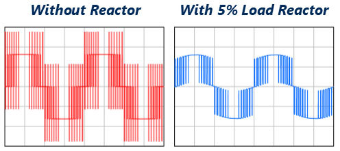
A reactor can also be placed on the load side of a VFD to help protect motors by acting as a useful buffer in between the drive and motor. A standard Pulse Width Modulated (PWM) drive produces a square wave power supply to the electric motor. That modulated square waveform has sharp edges on the waveform transitions.
Using modern output transistors, the drive will simulate a usable wave form modulated at very fast speeds to vary the speed of the electric motor. That fast switching speed creates a problem for the motor, addressed as dv/dt, or the rise time and magnitude of the voltage on the edge of the cycle transitions. Those fast waveform pulses create the voltage distortion and spikes that can cause damage to the motors insulation system and shorten the motors service life. While inverter duty motors are designed to tolerate this condition, even the best insulation system will operate better and longer if the distortion is kept to a minimum. The design inductance of the line reactor will act to soften those sharp edges and slow down the distortion as the voltage is provided to the motor.

What are Load Reactors?
Line applied reactors help to stabilize the current waveform, and act as an impedance between the power source and VFD. That impedance will both protect the input section of the VFD and reduce the harmonic current drawn from the power system by the drive. Both line reactors and drive isolation transformers mitigate or resolve certain power problems that occur due to VFD operation, primarily by adding impedance to the supply line.
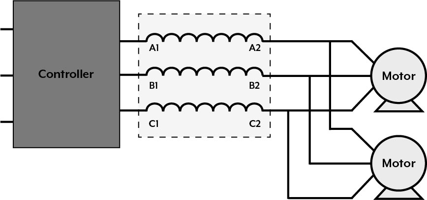
Load applied reactors provide a buffer in between the VFD and the motor to temper the waveform and reduce the voltage stress on the motor. By conditioning the waveform into a more suitable profile, the motor, and lead cable will operate cooler, thus putting less stress on the current carrying components of the drive application.
What are Some Side-Effects of Adding a Reactor?
Like most medication there are side-effects to using a reactor. Though these issues should not prevent the use of a reactor when one is required, the user should be aware of and ready to accommodate these effects. Since a reactor is made of wire (usually copper) wound in a coil, it will have the associated losses due to wire resistance. Also, if it is an Iron core inductor (as in the case of most reactors used in power electronics) it will have some “eddy current” loss in the core due to the changing magnetic field and the iron molecules being magnetically realigned. In general a reactor will add cost and weight, require space, generate heat and reduce efficiency.
Sometimes the addition of a line reactor can change the characteristics of the line you are connected to. Other components such as power factor correction capacitors and stray cable capacitance can interact with a line reactor causing a resonance to be set up. AC drives have exhibit a relatively good power factor and do not require the use of correction capacitors. In fact, power factor correction capacitors often do more harm than good where AC drives are present. For the most part, power factor correction capacitors should never be used with a drive. You may find that the addition of a reactor completes the required components for a line resonance where none previously existed, especially where power factor correction capacitors are present. In such cases either the capacitor or the inductor must be removed.
Furthermore, reactors have the effect of dropping some voltage, reducing the available voltage to the motor and or input of the motor drive.
