By Edward Cowern, P.E. – Baldor/ABB.
Introduction
Industrial electric motors have been available for nearly a century. In that time there have been a great many changes. One of the most obvious has been the ability to pack more horsepower in a smaller physical size. Another important achievement has been the standardization of motors by the National Electric Manufacturers Association (NEMA).
A key part of motor interchangeability has been the standardization of frame sizes. This means that the same horsepower, speed, and enclosure will normally have the same frame size from different motor manufacturers. Thus, a motor from one manufacturer can be replaced with a similar motor from another company provided they are both in standard frame sizes. Frame numbers are not intended to indicate electrical characteristics such as horsepower. However, as a frame number becomes higher, in general does the physical size of the motor and the horsepower. There are many motors of the same horsepower built in different frames. NEMA frame size refers to mounting only and has no direct bearing on the motor body diameter.

Three Generations
The standardization effort over the last forty years has resulted in one original grouping of frame sizes called “original”. In 1952, new frame assignments were made. These were called “U frames”. The current “T frames” were introduced in 1964. “T” frames are the current standard and most likely will continue to be for some time in the future.
Even though “T” frames were adopted in 1964, there are still a great many “U” frame motors in service that will have to be replaced in the future. Similarly there are also many of the original frame size motors (pre-1952) that will reach the end of their useful life and will have to be replaced. For this reason, it is desirable to have reference material available on frame sizes and some knowledge of changes that took place as a part of the so-called rerate programs.
In any standard frame number designation there are either two or three numbers. Typical examples of frame numbers are 48, 56, 145, and 215. The frame number relates to the “D” dimension (distance from center of shaft to center bottom of mount). For example, in the two-digit 56 frame, the “D” dimension is 3½”, 56 divided by 16 = 3½”. For the “D” dimension of a three-digit frame number, consider only the first two digits and use the divisor 4. In frame number 145, for example, the first two digits divided by the constant 4 is equal to the “D” dimension, 14 divided by 4 = 3½”. Similarly, the “D” dimension of a 213 frame motor is 5¼”, 21 divided by 4 = 5¼”. By NEMA definition, two-digit frame numbers are fractional frames even though 1 HP or larger motors may be built in them. Three-digit frame numbers are by definition integral frames. The third numeral indicates the distance between the mounting holes parallel to the base. It has no significance in a footless motor.
Frame Size Reference Tables
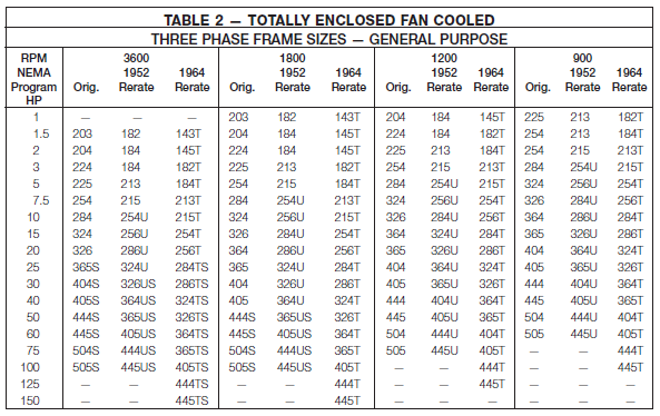
Tables 1 and 2 show the standard frame size assignments for the three different eras of motors. As you will note, these tables are broken down for open drip proof (table 1) and totally enclosed (table 2). Also, you will find that for each horsepower rating and speed, there are three different frame sizes. The first is the original frame size, the middle one is the “U frame” size, and the third one is the “T frame”. These are handy reference tables since they give general information for all three vintages of three phase motors in integral horsepower frame sizes.
One important item to remember is that the base mounting hole spacing (“E” and “F” dimensions) and shaft height (“D” dimension) for all frames having the same three digits regardless of vintage, will be the same.
Rerating and Temperatures
The ability to rerate motor frames to get more horsepower in a frame has been brought about mainly by improvements made in insulating materials. As a result of this improved insulation, motors can be run much hotter. This allows more horsepower in a compact frame. For example, the original NEMA frame sizes ran at very low temperatures. The “U” frame motors were designed for use with Class A insulation, which has a rating of 105° C. The motor designs were such that the capability would be used at the hottest spot within the motor. “T” frame motor designs are based on utilizing Class B insulation with a temperature rating of 130° C. This increase in temperature capability made it possible to pack more horsepower into the same size frame. To accommodate the larger mechanical horsepower capability, shaft and bearing sizes had to be increased. Thus, you will find that the original 254 frame (5 HP at 1800 RPM) has a 1-1/8″ shaft. The 254U frame (7-1/2 HP at 1800 RPM) has a 1-3/8″ shaft, and the current 254T frame (15 HP at 1800 RPM) has a 1-5/8″ shaft. Bearing diameters were also increased to accommodate the larger shaft sizes and heavier loads associated with the higher horsepowers.
Frame Size Basis
Bottom of the page you will find a Baldor frame size chart that is a great reference on “T” frame, “U” frame and original frame motors. Most of the dimensions are standard dimensions that are common to all motor manufacturers. One exception to this is the “C” dimension (overall motor length) which will change from one manufacturer to another.
Fractional Horsepower Motors

The term “fractional horsepower” is used to cover those frame sizes having two digit designations as opposed to the three digit designations that are found in Tables 1 and 2. The frame sizes that are normally associated with industrial fractional horsepower motors are 42, 48, and 56. In this case, each frame size designates a particular shaft height, shaft diameter, and face or base mounting hole pattern. In these motors, specific frame assignments have not been made by horsepower and speed, so it is possible that a particular horsepower and speed combination might be found in three different frame sizes. In this case, for replacement it is essential that the frame size be known as well as the horsepower, speed and enclosure. The derivation of the two digit frame number is based on the shaft height in sixteenths of an inch. You can figure that a 48 frame motor will have a shaft height of 48 divided by 16 or 3 inches. Similarly, a 56 frame motor would have a shaft height of 3-1/2 inches. The largest of the current fractional horsepower frame sizes is a 56 frame which is available in horsepowers greater than those normally associated with fractionals. For example, 56 frame motors are built in horsepowers up to 3 HP and in some cases, 5 HP. For this reason, calling motors with 2 digit frame sizes “fractionals” is somewhat misleading.
Integral Horsepower Motors
The term Integral Horsepower Motors generally refers to those motors having three digit frame sizes such as 143T or larger. When dealing with these frame sizes one “rule of thumb” is handy. It is that the centerline shaft height (“D” dimension) above the bottom of the base is the first two digits of the frame size divided by four. For example, a 254T frame would have a shaft height of 25 ÷ 4 = 6.25 inches. Although the last digit does not directly relate to an “inch” dimension, larger numbers do indicate that the rear bolt holes are moved further away from the shaft end bolt holes (the “F” dimension becomes larger).
Variations
In addition to the standard numbering system for frames, there are some variations that will appear. These are itemized below along with an explanation of what the various letters represent.
C – Designates a “C” face (flange) mounted motor. This is the most popular type of face mounted motor and has a specific bolt pattern on the shaft end to allow mounting. The critical items on “C” face motors are the “bolt circle” (AJ dimension), register (also called rabbet) diameter (AK dimension) and the shaft size (U dimension). C flange motors always have threaded mounting holes in the face of the motor.
D – The “D” flange has a special type of mounting flange installed on the shaft end. In the case of the “D” flange, the flange diameter is larger than the body of the motor and it has clearance holes suitable for mounting bolts to pass through from the back of the motor into threaded holes in the mating part. “D” flange motors are not as popular as “C” flange motors.
H – Used on some 56 frame motors, “H” indicates that the base is suitable for mounting in either 56, 143T, or 145T mounting dimensions.
J – This designation is used with 56 frame motors and indicates that the motor is made for “jet pump” service with a threaded stainless steel shaft and standard 56C face.
JM – The letters “JM” designate a special pump shaft originally designed for a “mechanical seal”. This motor also has a C face.
JP – Similar to the JM style of motor having a special shaft, the JP motor was originally designed for a “packing” type of seal. The motor also has a C face.
S – The use of the letter “S” in a motor frame designates that the motor has a “short shaft”. Short shaft motors have shaft dimensions that are smaller than the shafts associated with the normal frame size. short shaft motors are designed to be directly coupled to a load through a flexible coupling. They are not supposed to be used on applications where belts are used to drive the load.
T – A “T” at the end of the frame size indicates that the motor is of the 1964 and later “T” frame vintage.
U – A “U” at the end of the frame size indicates that the motor falls into the “U” frame size assignment (1952 to 1964) era.
Y – When a “Y” appears as a part of the frame size it means that the motor has a special mounting configuration. It is impossible to tell exactly what the special configuration is but it does denote that there is a special non-standard mounting.
Z – Indicates the existence of a special shaft which could be longer, larger, or have special features such as threads, holes, etc. “Z” indicates only that the shaft is special in some undefined way.

