By Leeson.
By definition, adjustable speed drives of any type provide a means of variably changing speed to better match operating requirements. Such drives are available in mechanical, fluid and electrical types.
The most common mechanical versions use combinations of belts and sheaves, or chains and sprockets, to adjust speed in set, select-able ratios – 2:1, 4:1, 8:1 and so forth. Traction drives, a more sophisticated mechanical control scheme, allow incremental speed adjustments. Here, output speed is varied by changing the contact points between metallic disks, or between balls and cones.
Adjustable speed fluid drives provide smooth, step-less adjustable speed control. There are three major types. Hydro-static drives use electric motors or internal combustion engines as prime movers in combination with hydraulic pumps, which in turn drive hydraulic motors. Hydro-kinetic and hydro-viscous drives directly couple input and output shafts. Hydro-kinetic versions adjust speed by varying the amount of fluid in a vortex that serves as the input-to-output coupler. Hydro-viscous drives, also called oil shear drives, adjust speed by controlling oil-film thickness, and therefore slippage, between rotating metallic disks.
An eddy current drive, while technically an electrical drive, nevertheless functions much like a hydro-kinetic or hydro-viscous fluid drive in that it serves as a coupler between a prime mover and driven load. In an eddy current drive, the coupling consists of a primary magnetic field and secondary fields created by induced eddy currents. The amount of magnetic slippage allowed among the fields controls the driving speed.
In most industrial applications, mechanical, fluid or eddy current drives are paired with constant-speed electric motors. On the other hand, solid state electrical drives (also termed electronic drives), create adjustable speed motors, allowing speeds from zero RPM (Revolutions Per Minute ) to beyond the motor’s base speed. Controlling the speed of the motor has several benefits, including increased energy efficiency by eliminating energy losses in mechanical speed changing devices. In addition, by reducing, or often eliminating, the need for wear-prone mechanical components, electrical drives foster increased overall system reliability, as well as lower maintenance costs. For these and other reasons, electrical drives are the fastest growing type of adjustable speed drive.
There are two basic drive types related to the type of motor controlled – DC and AC. A DC direct current drive controls the speed of a DC motor by varying the armature voltage (and sometimes also the field voltage). An alternating current drive controls the speed of an AC motor by varying the frequency and voltage supplied to the motor.
DC Drives
Direct current drives are easy to apply and technologically straightforward. They work by rectifying AC voltage from the power line to DC voltage, then feeding adjustable voltage to a DC motor. With permanent magnet DC motors, only the armature voltage is controlled. The more voltage supplied, the faster the armature turns. With wound-field motors, voltage must be supplied to both the armature and the field. In industry, the following three types of DC drives are most common:
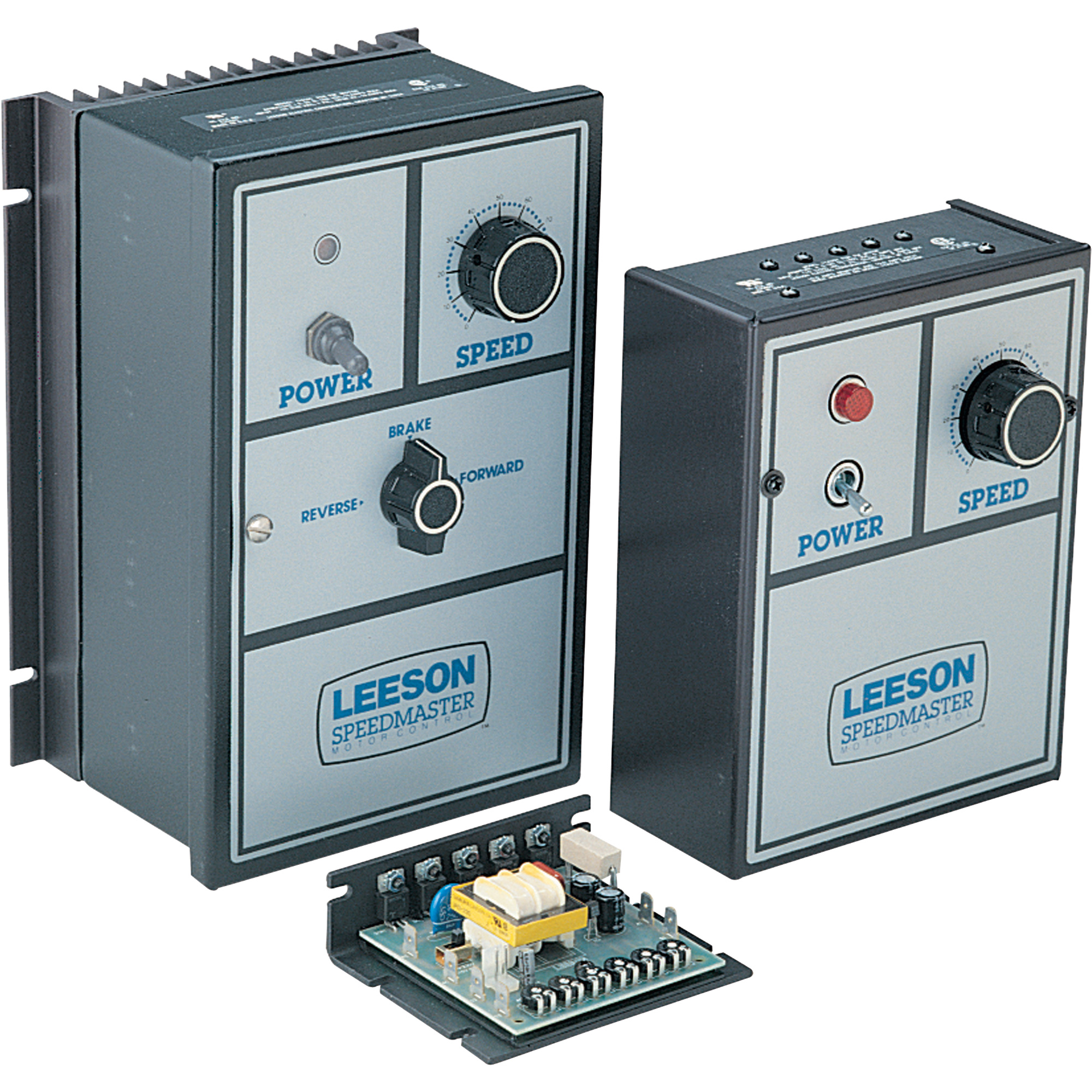
From left, NEMA 4/12 “totally enclosed” version, chassis-mount, NEMA 1 “open” enclosure.
DC SCR Drives: These are named for the silicon controlled rectifiers (SCR, also called thyristors) used to convert AC to controlled voltage DC. Inexpensive and easy to use, these drives come in a variety of enclosures, and in unidirectional or reversing styles.
Regenerative SCR Drives: Also called four quadrant drives, these allow the DC motor to provide both motoring and braking torque. Power coming back from the motor during braking is regenerated back to the power line and not lost.
Pulse Width Modulated DC Drives: Abbreviated PWM (Pulse Width Modulation) and also called, generically, transistorized DC drives, these provide smoother speed control with higher efficiency and less motor heating. Unlike SCR drives, PWM types have three elements. The first converts AC to DC, the second filters and regulates the fixed DC voltage, and the third controls average voltage by creating a stream of variable width DC pulses. The filtering section and higher level of control modulation account for the PWM drive’s improved performance compared with a common SCR drive.
AC Drives
AC drive operation begins in much the same fashion as a DC drive. Alternating line voltage is first rectified to produce DC. But because an AC motor is used, this DC voltage must be changed back, or inverted, to an adjustable-frequency alternating voltage. The drive’s inverter section accomplishes this. In years past, this was accomplished using SCRs. However, modern AC drives use a series of transistors to invert DC to adjustable-frequency AC.

This synthesized alternating current is then fed to the AC motor at the frequency and voltage required to produce the desired motor speed. For example, a 60hz synthesized frequency, the same as standard line frequency in the United States, produces 100% of rated motor speed. A lower frequency produces a lower speed, and a higher frequency a higher speed. In this way, an AC drive can produce motor speeds from, approximately, 15 to 200% of a motor’s normally rated RPM – by delivering
frequencies of 9hz to 120hz, respectively.
Today, AC drives are becoming the systems of choice in many industries. Their use of simple and rugged three-phase induction motors means that AC drive systems are the most reliable and least maintenance prone of all. Plus, microprocessor advancements have enabled the creation of so-called vector drives, which provide greatly enhance response, operation down to zero speed and positioning accuracy. Vector drives, especially when combined with feedback devices such as tachometers, encoders and
resolvers in a closed-loop system, are continuing to replace DC drives in
demanding applications.
By far the most popular AC drive today is the pulse width modulated type. Though originally developed for smaller-horsepower applications, PWM is now used in drives of hundreds or even thousands of horsepower – as well as remaining the staple technology in the vast majority of small integral and fractional horsepower “micro” and “sub-micro” AC drives.
Pulse width modulated refers to the inverter’s ability to vary the output voltage to the motor by altering the width and polarity of voltage pulses. The voltage and frequency are synthesized using this stream of voltage pulses. This is accomplished through microprocessor commands to a series of power semiconductors that serve as on-off switches. Today, these switches are usually IGBTs (Insulated Gate Bipolar Transistors), or isolated gate bipolar transistors. A big advantage to these devices is their fast switching speed resulting in higher pulse or carrier frequency, which minimizes motor noise.
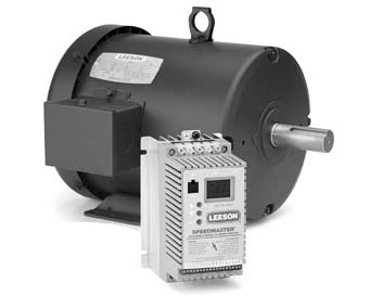
“One Piece” Motor/Drive Combinations
Variously called intelligent motors, smart motors or integrated motors and drives, these units combine a three-phase electric motor and a pulse width modulated inverter drive in a single package. Some designs mount the drive components in what looks like an oversize conduit box. Other designs integrate the drive into a special housing made to blend with the motor. A supplementary cooling fan is also frequently used for the drive electronics to counteract the rise in ambient temperature caused by being in close proximity to an operating motor. Some designs also encapsulate the inverter boards to guard against damage from vibration.
Size constraints limit integrated drive and motor packages to the smaller horsepower ranges and require programming by remote keypad, either hand-held or panel mounted. Major advantages are compactness and elimination of additional wiring.
AC Drive Application Factors
As PWM AC drives have continued to increase in popularity, drives manufacturers
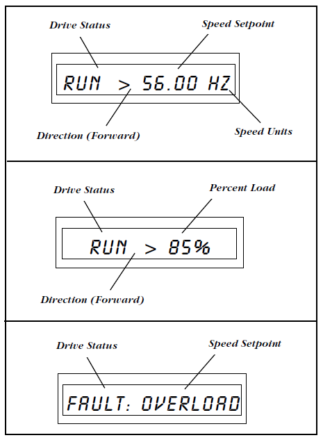
have spent considerable research and development effort to build in programmable acceleration and deceleration ramps, a variety of speed presets, diagnostic abilities, and other software features. Operator interfaces have also been improved with some drives incorporating “plain English” readouts to aid set-up and operation. Plus, an array of input and output connections, plug-in programming modules, and off-line programming tools allow multiple drive set-ups to be installed and maintained in a fraction of the time spent previously. All these features have simplified drive applications. However, several basic points must be considered:
Torque: This is the most critical application factor. All torque requirements must be assessed, including starting, running, accelerating and decelerating and, if required, holding torque. These values will help determine what current capacity the drive must have in order for the motor to provide the torque required. Usually, the main constraint is starting torque, which relates to the drive’s current overload capacity. (Many drives also provide a starting torque boost by increasing voltage at lower frequencies.)
Perhaps the overriding question, however, is whether the application is variable torque or constant torque. Most variable torque applications fall into one of two categories – air moving or liquid moving – and involve centrifugal pumps and fans. The torque required in these applications decreases as the motor RPM decreases. Therefore, drives for variable torque loads require little overload capacity. Constant torque applications, including conveyors, positive displacement pumps, extruders, mixers or
other “machinery” require the same torque regardless of operating speed, plus extra torque to get started. Here, high overload capacity is required.
Smaller-horsepower drives are often built to handle either application. Typically, only a programming change is required to optimize efficiency (variable volts-to-hertz ratio for variable torque loads, constant volts-to-hertz ratio for constant torque loads). Larger horsepower drives are usually built specifically for either variable or constant torque applications.
Speed: As mentioned, AC drives provide an extremely wide speed range. In addition, they can provide multiple means to control this speed. Many drives, for example, include a wide selection of preset speeds, which can make set-up easier. Similarly, a range of acceleration and deceleration speed “ramps” are provided. Slip compensation, which maintains constant speed with a changing load, is another feature that can be helpful. In addition, many drives have programmable “skip frequencies.” Particularly with fans or pumps, there may be specific speeds at which vibration takes place. By programming the drive to avoid these corresponding frequencies, the vibration can be minimized. Another control function, common with fans, is the ability for the drive to start into a load already in motion – often called a rolling start or spinning start. If required, be sure your drive allows this or you will face over-current tripping.
Current: The current a motor requires to provide needed torque is the basis for sizing a drive. Horsepower ratings, while listed by drives manufacturers as a guide to the maximum motor size under most applications, are less precise. Especially for demanding constant torque applications, the appropriate drive may, in fact, be “oversized” relative to the motor. As a rule, general-purpose constant torque drives have an overload current capacity of approximately 150% for one minute, based on nominal output. If an application exceeds these limits, a larger drive should be specified.
Power Supply: Drives tolerate line-voltage fluctuations of 10-15% before tripping and are sensitive to power interruptions. Some drives have “ride-through” capacity of only a second or two before a fault is triggered, shutting down the drive. Drives are sometimes programmed for multiple automatic restart attempts. For safety, plant personnel must be aware of this. Manual restart may be preferred.
Most drives require three-phase input. Smaller drives may be available for single-phase input. In either case, the motor itself must be three-phase.
Drives, like any power conversion device, create certain power disturbances (called “noise” or “harmonic distortion”) that are reflected back into the power system to which they are connected. These disturbances rarely affect the drive itself but can affect other electrically sensitive components.
Control Complexity: Even small, low-cost AC drives are now being produced with impressive features, including an array of programmable functions and extensive input and output capability for integration with other components and control systems. Additional features may be offered as options. Vector drives, as indicated previously, are one example of enhanced control capability for specialized applications.
In addition, nearly all drives provide some measure of fault logging and diagnostic capability. Some are extensive, and the easiest to use display the information in words and phrases rather than simply numerical codes.
Environmental Factors: The enemies of electronic components are well-known. Heat, moisture, vibration and dirt are chief among them and obviously should be mitigated. Drives are rated for operation in specific maximum and minimum ambient temperatures. If the maximum ambient is exceeded, extra cooling must be provided, or the drive may have to be oversized. High altitudes, where thinner air limits cooling effectiveness, call for special consideration. Ambient temperatures too low can allow
condensation. In these cases, or where humidity is generally high, a space heater may be needed.
Drive enclosures should be selected based on environment. (National Electrical Manufacturers Association) NEMA 1 enclosures are ventilated and must be given room to “breath.” NEMA 4/12 enclosures, having no ventilation slots, are intended to keep dirt out and are also used in wash-down areas. Larger heat sinks provide convection cooling and must not be obstructed, nor allowed to become covered with dirt or dust. Higher-horsepower drives are typically supplied within NEMA rated enclosures. “Sub-micro” drives, in particular, often require a
customer-supplied enclosure in order to meet NEMA and National Electrical Code standards. The enclosures of some “micro” drives, especially those cased in plastic, may also not be NEMA rated.