By Lenze/AC Tech.
Affinity Laws
Most HVAC systems are designed to perform during peak load conditions that rarely occur during the year. Various flow control methods such as inlet guide vanes, discharge dampers, and throttling valves have been used to regulate flow during the majority of the year when demand is less than full capacity. While these methods can effectively control flow, they are very inefficient and therefore waste a lot of energy because they do not take advantage of the Affinity Laws. The Affinity Laws govern the flow of fluids such as air and water.
The Affinity Laws state the following:
• Flow is directly proportional to speed
• Torque required is proportional to speed squared
• Horsepower required is proportional to speed cubed

The Affinity Laws are shown graphically above. This clearly shows that reducing the fan or pump speed, even slightly, results in a large reduction in required horsepower. This adds up to significant energy savings. For example, at 50% flow, the horsepower required is only 12.5% (0.53 = 0.125 = 12.5%). For a 50 Hp motor, this means only 6.25 Hp is required. It would actually cost less to run two 50 Hp motors at 50% speed than it would to run one 50 Hp motor at 100% speed!
THE MCH SERIES VFD vs. OTHER FLOW CONTROL METHODS
The MCH Series VFD (variable frequency drive) saves energy as shown above by reducing the actual speed of the pump or fan when full flow is not required. In other flow control methods, the motor always runs at full speed and the flow is mechanically restricted. While these methods can save some energy at reduced flows, they cannot match the savings that can be achieved using an MCH Series VFD.
ADDITIONAL BENEFITS OF THE MCH SERIES VFD
PID SETPOINT CONTROL: The built-in PID feature allows the MCH Series VFD to maintain a desired process setpoint (such as PSI or GPM) by constantly adjusting the motor speed based on a process feedback signal. This provides very precise process control, which saves additional energy by exactly matching demand. This feature also reduces installation costs because it eliminates the need for a separate PID controller. Only a feedback transducer is required to make the MCH Series VFD a complete process control system.
SOFT-STARTING: Ramping the motor up to speed eliminates the peak current and shock-load conditions that stress the driven equipment. This further reduces energy costs, and also reduces maintenance costs and downtime.
CENTRIFUGAL FANS
Centrifugal fans are commonly used to distribute air in HVAC systems. Two of the most common methods of flow control for fans are discharge dampers and inlet guide vanes. The diagram below compares the power requirements of discharge dampers and inlet guide vanes to direct variable flow control using the MCH Series VFD. Also shown is the theoretical power requirement defined by the Affinity Laws.
Typical Applications
• Supply and Return Fans
• Exhaust Fans
• Boiler Fans
• Fume Hood Fans
• Kiln Fans
SIGNIFICANT ENERGY SAVINGS AND FAST PAYBACK

Due to system inefficiencies, the theoretical Affinity Law power requirement cannot be achieved, but controlling flow using the MCH Series VFD is very close. It’s easy to see from the diagram above that the energy savings compared to other flow control methods is dramatic. For example, operating at 50% flow requires only about 18% power using the MCH Series, while the discharge damper requires about 90% and the guide vanes require about 60%. This tremendous energy savings potential results in typical paybacks of less than one year!
BETTER PROCESS CONTROL
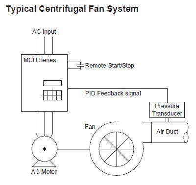
Using the built-in PID Setpoint Control feature, the MCH Series VFD can maintain a desired pressure by constantly adjusting the fan speed to match demand.
In the example to the right, a transducer is used to provide a feedback signal that represents the actual system pressure. The VFD compares this feedback signal to the desired setpoint, and adjusts the fan speed based on the error between the two. By always trying to eliminate the error, the VFD maintains the desired pressure.
CENTRIFUGAL PUMPS
Centrifugal pumps are used in a wide variety of commercial, industrial, and municipal applications, and throttling valves are a common flow control method. The diagram below compares the power requirements of a throttling valve to that of the MCH Series VFD. Also shown is the theoretical power requirement defined by the Affinity Laws.
Typical Applications
• Chilled and Hot Water Pumps
• Condenser Water Pumps
• Booster Pumps
• Potable Water Pumps
• Chemical Pumps
SIGNIFICANT ENERGY SAVINGS AND FAST PAYBACK

Due to system inefficiencies, the theoretical Affinity Law power requirement cannot be achieved, but controlling flow using the MCH Series VFD is very close. It’s easy to see from the diagram above that the energy savings is dramatic compared to the throttling valve.
For example, operating at 75% flow requires only about 50% power using the MCH Series, while the throttling valve requires about 90%. This tremendous energy savings potential results in typical paybacks of less than one year!
BETTER PROCESS CONTROL

The built-in PID Setpoint Control feature in the MCH Series VFD allows it to maintain a desired pressure or temperature by constantly adjusting pump speed.
In the example to the right, a transducer is used to provide a feedback signal that represents the actual system pressure. The VFD compares this feedback signal to the desired setpoint, and adjusts the pump speed based on the error between the two. By always trying to eliminate the error, the VFD maintains the desired pressure.
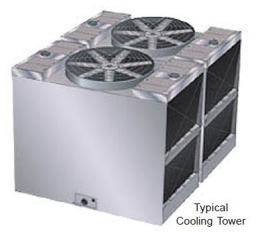
COOLING TOWERS
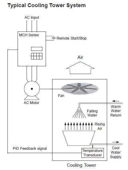
Cooling towers are common in HVAC systems and are used to cool water. They do this by using fans to blow air through falling water. The water temperature is reduced as the heat is transferred to the air and expelled in the form of evaporation.
To achieve the desired water temperature, some cooling towers simply cycle the fan on and off, or use a 2 speed fan motor. Other cooling towers have multiple fans that are staged according to demand.
The absence of an air flow control method (such as vanes or dampers) means that the cooling tower fans operate at 100% flow and therefore require 100% energy. Also, cycling of the fan (or fans) on and off increases mechanical stress on the driven equipment and results in high peak currents.
Applying an MCH Series VFD to a cooling tower will result in dramatic energy savings (see the Centrifugal Fans section of this guide for more information). The PID feature in the MCH Series allows the water temperature to be controlled precisely by varying the speed of the fan (or fans) that control the air flow.
A temperature transducer measures the actual water temperature and is the feedback to the MCH Series VFD. The VFD compares the actual water temperature to the desired temperature setpoint, and adjusts the fan speed accordingly. If the temperature is too high, the VFD will increase the air flow to reduce the water temperature back to the desired setpoint. If the temperature is too low, the VFD will decrease the air flow to reduce the cooling effect.
COOLING TOWER DE-ICING
In cold climates, the movement of air through the cooling tower can result in ice forming, ultimately resulting in either damage to the cooling tower or preventing water flow in the system. To eliminate ice build up, the fan motor can be operated in reverse, which moves warm air over the ice, causing it to thaw. This procedure needs to be done manually and regularly during icing conditions to keep the ice from reaching a critical build-up.
This method of de-icing is losing favor for a more automated system that senses ice forming conditions and stops the airflow to prevent the condition. The MCH Series VFD can be configured to work in either case. Ice sensors can be easily interfaced to the VFD to shut down the fan, and the MCH Series has a “deicing” function that allows the motor to be manually operated in reverse rotation.
